05 - Closed Loop Systems
1. Control of Liquid Level
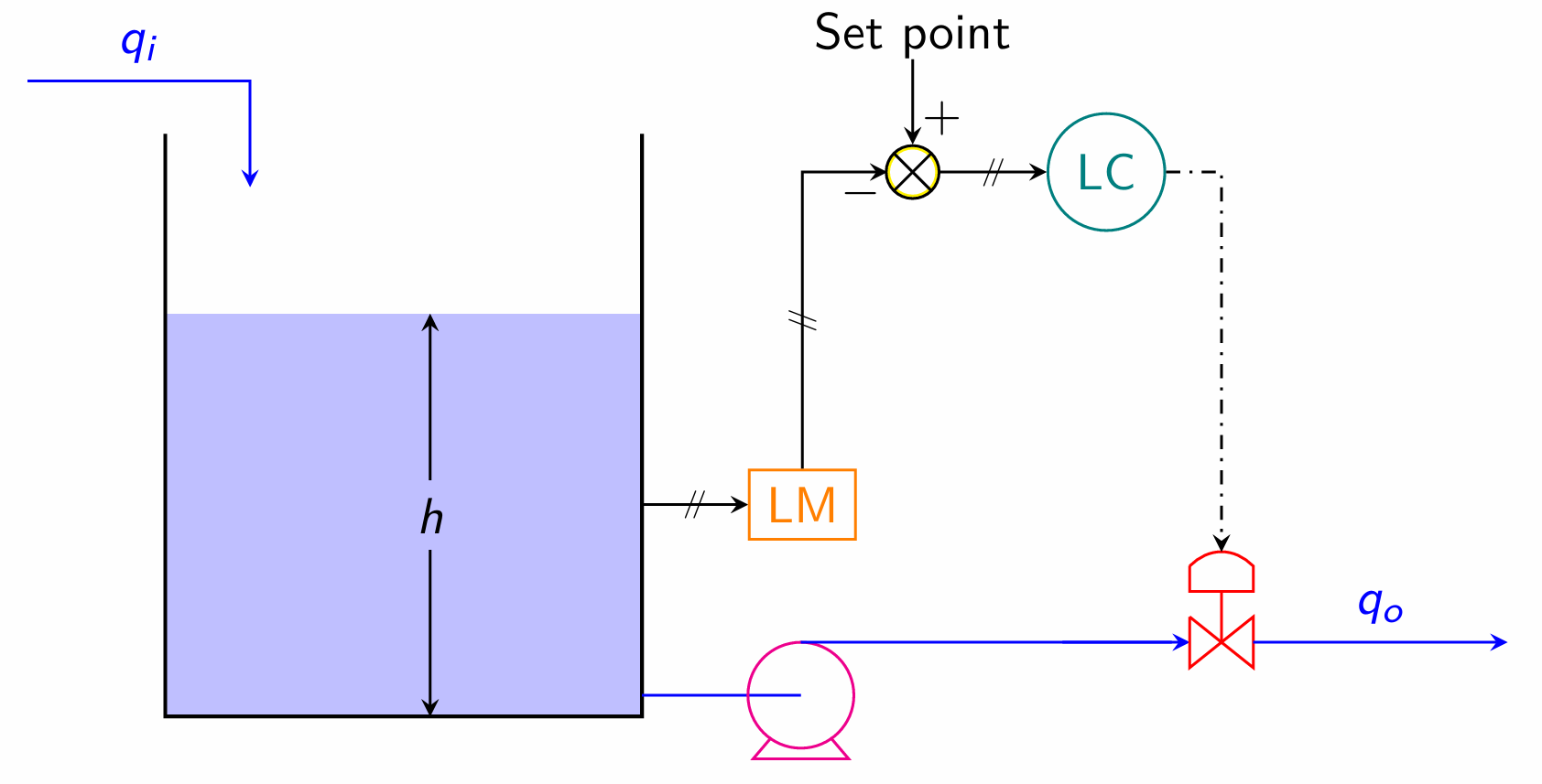
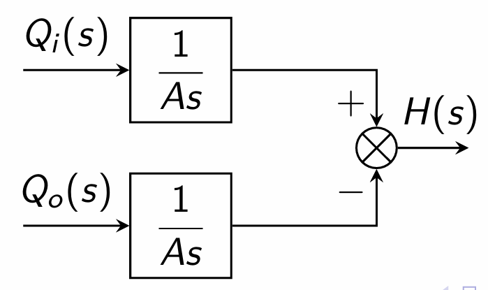
Tank dynamics: \[q_i - q_o = A\frac{dh}{dt}\] In terms of deviation variables, \[Q_i - Q_o = A\frac{dH}{dt}\] Taking Laplace transforms, and rearranging, \[H(s) = \frac{1}{As}\bigl(Q_i(s) - Q_o(s)\bigr) = G_d Q_i(s) - G_pQ_o(s)\]
Block Diagram Representation:
Outflow from the pump is regulated by a control valve (the final control element), dynamics of which is given by \[Q_o(s) = \frac{K_v}{\tau_v s+1}C(s) \qquad \Longrightarrow \quad Q_o(s) = G_f C(s)\] Signal to the control valve is from a controller (typically a PID controller), and the dynamics of which is given by \[C(s) = G_c\epsilon(s)\] For the PID controller, \[G_c = K_c\left(1+\frac{1}{\tau_Is}+\tau_Ds \right)\]
Signal to the controller is the error amount. i.e., \[\epsilon(s)=H_{sp}(s)-H_m(s)\]
The measurement device for level may be differential pressure cell (DPC), which has second order dynamics, as given by \[\frac{H_m(s)}{H(s)} = \frac{K_m}{\tau^2s^2 + 2\tau\zeta s+1} \qquad \Longrightarrow \quad H_m(s) = G_m H(s)\]
Hence, for the closed loop \[\begin{aligned} H(s) &= G_dQ_i(s) - G_pQ_o(s) \\ &= G_dQ_i(s) - G_pG_fC(s) \\ &= G_dQ_i(s) - G_pG_fG_c\epsilon(s) \\ &= G_dQ_i(s) - G_pG_fG_c\bigl[H_{sp}(s)-H_m(s)\bigr] \\ &= G_dQ_i(s) - G_pG_fG_c\bigl[H_{sp}(s)-G_mH(s)\bigr] \\ (1- G_pG_fG_cG_m)H(s) &= G_dQ_i(s) - (G_pG_fG_c)H_{sp}(s) \\ H(s) &= \frac{G_d}{1-G_pG_fG_cG_m}Q_i(s) - \frac{G_pG_fG_c}{1-G_pG_fG_cG_m}H_{sp}(s) \end{aligned}\]