Notes - Heat Exchangers
6.4 Shell and Tube Heat Exchangers
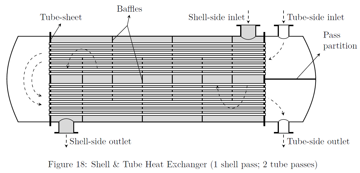
In this indirect contact type or surface heat exchanger there is no mixing of fluid. Refer to Fig.(18) for constructional aspects of shell-and-tube heat exchanger.
Refer to Fig.(19) for temperature profiles in 1-1 shell and tube exchanger.

Parallel Flow Exchangers
-
In a parallel flow heat exchanger, the outlet temperature of the cold fluid can not exceed that of the hot fluid. Therefore, the temperature effectiveness of the parallel flow exchangers is limited. Because of this limitation, generally they are not considered for heat recovery. However, since the metal temperature lies approximately midway between the hot and cold fluid temperatures, the wall is almost at a uniform temperature.
-
Parallel flow is used for cold viscous fluids, since the arrangement may enable a high value of \(U\) to be obtained.
Counter Flow Exchangers
-
In a counterflow exchanger, the exit temperature of the cold fluid can be higher than that of the hot fluid. Theoretically, the exit temperature of one fluid may approach the inlet temperature of the other. Therefore, the thermal capacity of the counterflow exchanger can be twice that of the parallel flow exchanger.
-
In a pure counter flow heat exchanger, the temperature rise in the cold fluid is equal to temperature drop in the hot fluid; thus the temperature difference \(\Delta T\) between the hot and cold fluids is constant throughout.
-
The high heat recovery and temperature effectiveness of this exchanger makes it preferable to the parallel flow exchanger whenever the design requirements permit such a choice. The metal temperature in the counterflow exchanger, in contrast to that of the parallel flow one, involves a steep gradient along the path of flow.
Fluid Allocation in Shell and Tube Exchangers
-
Corrosion: Fewer costly alloy components are needed if the corrosive fluid is inside the tubes. Corrosive fluid cannot be sent in the shell side, since the shell side fluid will affect both shell and tubes.
-
Fouling: Placing the fouling fluid inside the tubes allow better velocity control; increased velocities tend to reduce fouling. Straight tubes allow mechanical cleaning without removing the tube bundle.
-
Temperature & Pressure: For high temperature / pressure services requiring special or expensive alloy materials, fewer alloy components are needed when hot fluid is placed within the tubes
-
Flow rate: Placing the fluid with the lower flow rate on the shell side usually results in a more economical design. Turbulence exists on the shell side at much lower velocities than within the tubes.