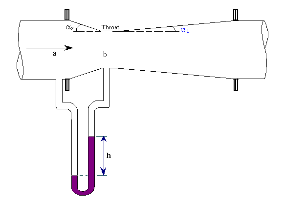
Venturi Meter
In this meter the fluid is accelerated by its passage through a converging cone of angle 15-20o. The pressure difference between the upstream end if the cone and the throat is measured and provides the signal for the rate of flow. The fluid is then retarded in a cone of smaller angle (5-7o) in which large proportion of kinetic energy is converted back to pressure energy. Because of the gradual reduction in the area there is no vena contracta and the flow area is a minimum at the throat so that the coefficient of contraction is unity.
The attraction of this meter lies in its high energy recovery so that it may be used where only a small pressure head is available, though its construction is expensive.

To make the pressure recovery large, the angle of downstream cone is small, so boundary layer separation is prevented and friction minimized. Since separation does not occur in a contracting cross section, the upstream cone can be made shorter than the downstream cone with but little friction, and space and material are thereby conserved.
Although venturi meters can be applied to the measurement of gas, they are most commonly used for liquids. The following treatment is limited to incompressible fluids.
The basic equation for the venturi meter is obtained by writing the Bernoulli equation for incompressible fluids between the two sections a and b. Friction is neglected, the meter is assumed to be horizontal.
If va and vb are the average upstream and downstream velocities, respectively, and r is the density of the fluid,
\[V_b^2 - v_a^2 = 2\frac{(p_a - p_b)}{\rho} → 1\]
The continuity equation can be written as,
va = (Db/Da)2vb = b2vb à 2
\[v_a = (\frac{D_b}{D_a})^2v_b} = b^2 v_b → 2\]
where Da = diameter of pipe
Db = diameter of throat of meter
b = diameter ratio, Db/Da
If va is eliminated from equn.1 and 2, the result is
 à 3
à 3
\[v_b = \frac{1}{\sqrt{1 - \beta^4}} \sqrt{\frac{2(p_a - p_b)}{\rho}} → 3\]
Equn.3 applies strictly to the frictionless flow of non-compressible fluids. To account for the small friction loss between locations a and b, equn.3 is corrected by introducing an empirical factor Cv. The coefficient Cv is determined experimentally. It is called the venturi coefficient, velocity of approach not included. The effect of the approach velocity va is accounted by the term 1/(1-b4)0.5. When Db is less than Da/4, the approach velocity and the term b can be neglected, since the resulting error is less than 0.2 percent.
For a well designed venturi, the constant Cv is about 0.98 for pipe diameters of 2 to 8 inch and about 0.99 for larger sizes.
In a properly designed venturi meter, the permanent pressure loss is about 10% of the venturi differential (pa - pb), and 90% of differential is recovered.
Volumetric flow rate:
The velocity through the venturi throat vb usually is not the quantity desired. The flow rates of practical interest are the mass and volumetric flow rates through the meter.
Volumetric flow rate is calculated from,
\[Q = \rho A_a v_b\] and mass flow rate from,
Mass flow rate = volumetric flow rate x density
The standard dimensions for the meter are:
Entrance cone angle \[(2\alpha_1) = 21 \pm 2^{\circ}\]
Exit cone angle \[(2\aloha_2a2) = 5 to 15^{\circ}\]
Throat length = one throat diameter
